VENTS A 150 PR
- Description
- Characteristics
- Downloads
- Dimensions
- Additional diagrams
Description
Description
| APPLICATION | |
|
|
| DESIGN | |
|
|
Characteristics
Characteristics
| Parameter |
A 150 PR |
Measurement unit |
|---|---|---|
| Air pass | 0.011 | m² |
| Connected air duct size | 150 | mm |
Damper normal pitch  |
0...21 | mm |
| Material | Пластиковые | - |
| Form | Rund | - |
| Adjustment | adjustable | - |
| Form | round | - |
| Connection diameter | 150 | mm |
| Material | plastic | - |
Files archieve
Downloads
Select document type
Dimensions
Characteristics

| Parameter | Value | Measurement unit |
|---|---|---|
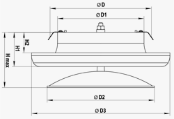
| D | 150 | mm |
| D1 | 125 | mm |
| D2 | 155 | mm |
| D3 | 200 | mm |
H max 
|
80.5 | mm |
| H1 | 50 | mm |
H2 
|
30 | mm |
Additional diagrams
Additional diagrams
The internal part of the air disk valve is pulled out to ensure the required clearance S (mm) to provide required air flow according to the diagram.


 Domestic fans
  Industrial and commercial fans
  Single-room ventilation systems with heat recovery
  Air handling units
  Air heating systems
  Smoke extraction and ventilation
  Accessories for ventilating systems
  Electrical accessories
  Ventilation ducts and fittings
  Air distribution components
  Ventilation kits and vents


