Login

Privacy Policy (GDPR)
Authorization
Not registered yet? Take advantages of registration:
Products saving in a binding to the projects
Product consultation from our experts - Online
Registration
Signup
By using this form, you confirm that you have read the site terms of use Terms of use and completely accept the terms of use

VENTS KP-2-O-N-1000x1000-2-...-SN-O

  • Description
  • Characteristics
  • Downloads
  • Dimensions
  • Designation key
  • BIM
  • Characteristics of actuators
  • Electrical connections
Description
Description
APPLICATION  
  • The fire dampers are intended for automatic closing of process openings and air duct penetrations in intermediate floors, walls and partitions, as well as closing of openings in supply and exhaust ducts of smoke ventilation systems.
  • The dampers of this particular design are not suitable for installation in air ducts and ducts of premises with rated explosion and fire safety category A and B and in flammable and explosive mixture intakes. The KP-2 fire-resisting duct dampers are capable of resisting fire for at least 120 minutes (EI 120) at the temperature of 600 °C.
DESIGN  
  • The KP-2 series dampers are made in the generalpurpose industrial version with a minimized variety of hardware components using low-alloy galvanized steel. The damper flap is made of fire-resistant material. The duct installation design results in two mounting flanges on the casing for integration into a ventilation ducts (air ducting) and external configuration of the drive mechanism for easier maintenance.
  • The KP-2...PKP/KP-2...PVP/KP-2...PSP dampers are equipped with a hot and cold zone baffle.
  • The KP-2...PKP/KP-2...PVP/KP-2...PSP series dampers are equipped with an electric actuator with a built-in return spring and a back-up thermal breaker.
  • Setting the damper to operating position (direct fire contact): remotely, via electric actuator.
  • The damper can be set to the operating or protective position either remotely via the control panel or manually using the manual cocking handle which is always included in the standard delivery set of the electric actuator. In case of the remote control panel failure, the back-up thermal breaker interrupts the power supply to the electric actuator and the return spring sets the damper to the operating position. Emergency damper actuation: the damper flap is set to the protective position automatically (damper unaffected by fire).
  • The electric actuator remains energized at all times. In case of an emergency actuation (direct fire contact): the electric actuator equipped with a return spring is de-energized and the damper flap is set to the operating position by means of the spring energy. In case of a power failure not related to fire and its subsequent restoration at the actuator with a return spring, the damper flap returns to protective position.
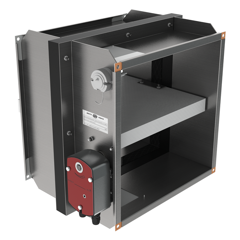
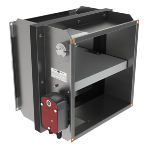
THE KP-2...PKP/KP-2...PVP/KP-2...PSP FIRE SAFETY DAMPER WITH BELIMO ELECTRIC ACTUATOR AND THERMOELECTRIC BREAKER
INSTALLATION  
  • The damper must be installed into the building envelope structure in accordance with the applicable standards and regulations.
  • The seal fire resistance must be at least equal to that of the building envelope.
  • The dampers can be installed in any position in vertical and horizontal ducts of fire-protection structures.
  • The ducts for damper installation must be made in such a way so as to prevent the transfer of loads caused by the fire-protection structures to the damper casing.
  • The adjoining air duct must be suspended in such a way so as to prevent the transfer of air duct load to the damper flange.
  • The minimum free space for accessing the control parts must be at least 350 mm.
  • Make sure to arrange an inspection hole.
  • While carrying out the installation consider size K.
  • When two or more dampers are installed into the same fire-protection separation structure, the distance between the two adjacent dampers must be at least 200 mm.
  • If such installation is not possible, the damper casing part between the fire-protection separation space and the damper flap must be insulated with a suitable material pursuant to the applicable standards.
  • If such installation is not possible, the damper casing part between the fire-protection separation structure and the damper flap must be insulated with a suitable material pursuant to the applicable standards.
  • The damper control mechanism must be protected against damage and contamination.
  • The damper casing must not deform any deformation during embedding.
  • After the installation the flap must not catch against the damper casing while opening or closing.
  • The fire safety damper can be integrated into a tight wall structure - e.g. made of conventional concrete work of minimum width W = 100 mm or into a plasterboard wall of the necessary fire resistance class or into a tight ceiling structure - e.g. made of conventional concrete of minimum width W = 150 mm.
  • Do not use any foaming substances for sealing the damper in the separation structure.
INSTALLATION RECOMMENDATIONS FOR KP-2...PKP/KP-2...PVP/KP-2...PSP FIRE SAFETY DAMPERS WITH ELECTRIC ACTUATOR AND THERMOELECTRIC BREAKER
  in horizontal building structures
   
in vertical building structures duct modification with an air duct
Characteristics
Characteristics
Parameter KP-2-O-N-1000x1000-2-...-SN-O
Measurement unit
Flow area 0.96
Weight 87 kg
Files archieve
Downloads
Select document type
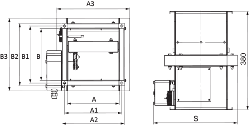
  • Advertising and printing products
  • Certificates
  • Technical documentation
Name
"KP-2" product description 03-2023 (pdf 1.47Mb)
Download high quality image "KP-2...PKP, KP-2...PVP, KP-2...PSP" (psd 2.57Mb)
Download image "KP-2...PKP, KP-2...PVP, KP-2...PSP" for your website (png 573.85Kb)
"Dampers KP, PL" user's manual 05-2023 (V58-1EN-04) (pdf 3.41Mb)
RFA models "KP-2" (rfa 896Kb)
Dimensions
Characteristics
VENTS KP-2-O-N-1000x1000-2-...-SN-O
Parameter Value Measurement unit
A 1000 mm
A1 1030 mm
A2 1060 mm
A3 1080 mm
B 1000 mm
B1 1030 mm
B2 1060 mm
B3 1080 mm
S 1150 mm
Designation key
Designation key

BIM
BIM

Characteristics of actuators
MAIN TECHNICAL SPECIFICATIONS OF BELIMO ELECTRIC ACTUATORS WITH A RETURN SPRING AND A THERMAL BREAKER
Technical data Basic models Models with increased torque Models with the highest torque
Rated operation voltage AC/DC 24 V AC 230 V AC/DC 24 V AC 230 V AC/DC 24 V AC 230 V
Permissible operating voltage tolerance AC 19.2…28.8 V
DC 21.6…28.8 V
АС 198…264 V AC 19.2…28.8 V
DC 21.6…28.8 V
АС 198…264 V AC 19.2…28.8 V
DC 21.6…28.8 V
АС 198…264 V
AC mains frequency 50/60 Hz
Power consumption at rest [W] 0.8 1.1 1.4 2.1 2 3
Power consumption in operation [W] 2.5 3.5 4 5 7 8.5
Maximum design capacity [VA] 4 6.5 6 10 10 11
Motor torque [Nm] 4 9 18
Spring torque [Nm] 3 7 12
SEC class III II III II III II
Ingress protection rating IP54
Auxiliary switches 2 pcs., single-pole, reversible 1 mA…3 (0.5) A, AC 250 V 2 pcs., single-pole, reversible, 1 mA…6(3)A, AC 250 V
Electric motor connection cable 1 m, 2 x 0.75 mm² (halogen-free)
Auxiliary switch connection cable 1 m, 6 x 0.75 mm² (halogen-free)
Running time spring 20 seconds at -10…+55 °С
< 60 seconds at -30…-10 °С
16 seconds at +20 °С
Running time motor < 60 s/90° < 120 s/90°
Response temperature of thermal breaker sensors Duct sensor 72 °С
Outdoor sensor 72 °С
Service life Min. 60 000 emergency positions
Technical maintenance Not required
 
MAIN TECHNICAL SPECIFICATIONS OF ZERN ELECTRIC ACTUATORS WITH A RETURN SPRING AND A THERMAL BREAKER
Technical data Basic models Models with increased torque
Rated operation voltage AC/DC 24 V AC 100-240 V AC/DC 24 V AC 100-240 V
Permissible operating voltage tolerance AC/DC 19.2…28.8 V АС 85…265 V AC/DC 19.2…28.8 V АС 85…265 V
AC mains frequency 50/60 Hz
Power consumption at rest [W] 3
Power consumption in operation [W] 5
Motor torque [Nm] 5 8
Spring torque [Nm]
SEC class III II III II
Ingress protection rating IP54
Auxiliary switches 2 pcs., single-pole, reversible, 1 mA…3(0.5)A, AC 220 V
Electric motor connection cable 1 m, 2 x 0.5 mm² (halogen-free)
Auxiliary switch connection cable 1 m, 6 x 0.5 mm² (halogen-free)
Running time spring < 20 seconds
< 60 seconds at -30…-10 °С
< 25 seconds
< 60 seconds at -30…-10 °С
Running time motor < 70 s/95° < 100 s/95°
Response temperature of thermal breaker sensors Duct sensor 72 °С
Outdoor sensor 72 °С
 
MAIN TECHNICAL SPECIFICATIONS OF SIEMENS ELECTRIC ACTUATORS WITH A RETURN SPRING AND A THERMAL BREAKER
Technical data Basic models Models with increased torque Models with the highest torque
Rated operation voltage AC 24 V
DC 24…48 V
AC 230 V AC 24 V
DC 24…48 V
AC 230 V AC 24 V
DC 24…48 V
AC 230 V
Permissible operating voltage tolerance AC/DC ±20% АС ±15% AC/DC ±20% АС ±15% AC/DC ±20% АС ±15%
AC mains frequency 50/60 Hz
Power consumption at rest [W] 2 3.5 2 3.5 3 4
Power consumption in operation [W] 3.5 4.5 3.5 4.5 5 6
Maximum design capacity [VA] 5 7 5 7 7 8
Motor torque [Nm] 4 9 18
Spring torque [Nm] 3 7 18
SEC class III II III II III II
Ingress protection rating IP54
Auxiliary switches 2 pcs., single-pole, reversible, 6(2)A, AC 24...250 V
Electric motor connection cable 0.9 m, 2 x 0.75 mm² (halogen-free)
Auxiliary switch connection cable 0.9 m, 6 x 0.75 mm² (halogen-free)
Running time spring 15 seconds
< 60 seconds at -30…-10 °С
Running time motor 90 s/90°
Response temperature of thermal breaker sensors Duct sensor 72 °С
Outdoor sensor 72 °С
Service life 10 000 emergency positions
Technical maintenance Not required
Electrical connections
ELECTRICAL CONNECTION OF THE BASIC MODELS OF BELIMO AND ZERN ELECTRIC ACTUATORS, AS WELL AS BELIMO AND ZERN MODELS WITH INCREASED TORQUE
 
ELECTRICAL CONNECTION OF BELIMO ELECTRIC ACTUATORS WITH THE HIGHEST TORQUE, AS WELL AS SIEMENS ELECTRIC ACTUATORS
Similar products
Share your opinion

Questionnaire
How often do you use equipment selection program?