Domestic fans
  Industrial and commercial fans
  Single-room ventilation systems with heat recovery
  Air handling units
  Air heating systems
  Smoke extraction and ventilation
  Accessories for ventilating systems
  Electrical accessories
  Ventilation ducts and fittings
  Air distribution components
  Ventilation kits and vents
 VENTS OKW1 600x350-3

- Description
- Characteristics
- Downloads
- Dimensions
- Additional diagrams
- Legend
| APPLICATION | |||||||||||||
|
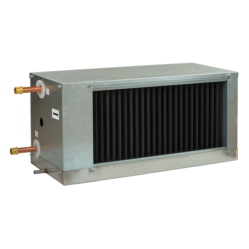
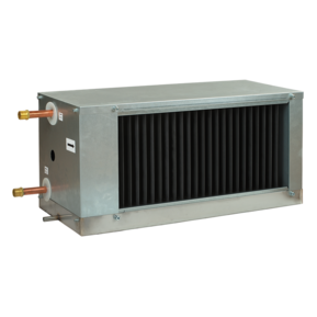
Duct water coil air coolers are designed for cooling of supply air in rectangular ventilation systems and can be applied in supply or supply and exhaust ventilation systems. |
|||||||||||||
| DESIGN | |||||||||||||
|
The water coolers are available in OKW and OKW1 mofications. The OKW1 cooler has a simplified design. The cooler casing is made of galvanized sheet steel, the manifold is made of copper tubes and the heat exchange surface is made of aluminium plates. The cooling coils are available in 3 rows modification and designed for the maximum operating pressure 1.5 MPa (15 bar). It is equipped with a droplet separator and a drain pan for condensate collection and removal. For OKW and OKW1 models by default the service side is located on the right side from the air stream direction. The OKW cooler service side location can be changed by coil turning by 180°. The OKW1 modification does not have this option. |
|||||||||||||
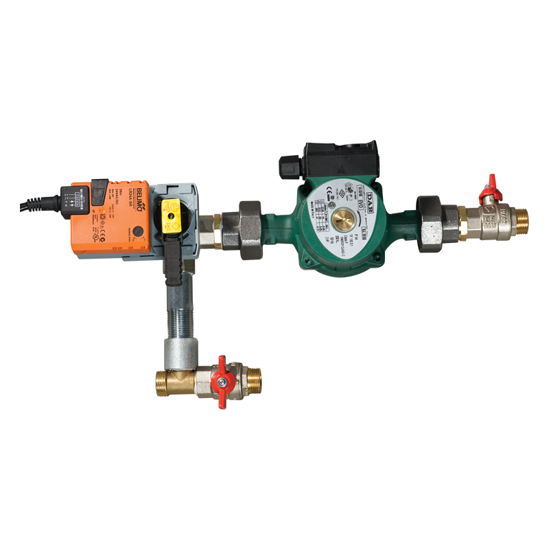
| MOUNTING | |||||||||||||
|
|||||||||||||
|
|
Н - U-trap height К - drain height Р - total pressure in the fan |
||||||||||||
|
|||||||||||||

  |
 |
| Counter flow connection | Parallel flow connection |
Air pressure loss in water coolers
Rectangular OKW1 series

| Parameter |
OKW1 600x350-3 |
Measurement unit |
|---|---|---|
Casing material  |
- | |
|
Rectangular duct size |
600х350 | mm |
| Width | 600 | mm |
| Height | 350 | mm |
| Weight | 17 | kg |
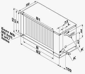
| Parameter | Value | Measurement unit |
|---|---|---|
| B | 600 | mm |
| B1 | 620 | mm |
| B2 | 780 | mm |
| H | 350 | mm |
| H1 | 370 | mm |
| H2 | 420 | mm |
|
H3
|
268 | mm |
| H4 | 229 | mm |
| L | 56 | mm |
|
K
|
G 3/4'' | mm |

How to use water cooler diagrams:
Air Speed. Starting from 2850 m3/h on the air flow scale draw a vertical line 1 till the air speed axis. It makes 3.85 m/s.
- Supply air temperature. Prolong the line 1 up to the point where it crosses the outside air temperature (e.g. +32°C); then draw a horizontal line 2 from this point to the left till crossing the outside air humidity (e.g. 50%). From this point draw a vertical line 3 to the supply air temperature at cooler outlet axis on top of the graphic (+20.7°C).
- Cooling capacity. Prolong the line 1 up to the point where it crosses the outside air temperature (e.g. +32°C) and draw a horizontal line 4 from this point to the right until it crosses the outside air humidity curve (e.g., 50%), from here draw a vertical line 5 up to the scale representing the cooling capacity (19.8 kW).
- Water flow. Prolong the line 5 down to water flow axis at the bottom of the graphic 6 (0.78 l/s).
- Water pressure drop. Draw the line 7 from the point where the line 6 crosses the black curve to the pressure drop axis(30.0 kPa).
| Series | Flange designation (WxH) [mm] | Number of cooling coils | ||
|---|---|---|---|---|
|
OKW1 |
400х200; 500х250; 500х300; 600х300; 600х350; 700х400; 800х500; 900х500; 1000х500 | 3 |