Login

Privacy Policy (GDPR)
Authorization
Not registered yet? Take advantages of registration:
Products saving in a binding to the projects
Product consultation from our experts - Online
Registration
Signup
By using this form, you confirm that you have read the site terms of use Terms of use and completely accept the terms of use

RNS-25

  • Description
  • Characteristics
  • Downloads
  • Dimensions
  • Wiring plan
Description
Description
APPLICATIONS DESIGN AND CONTROL
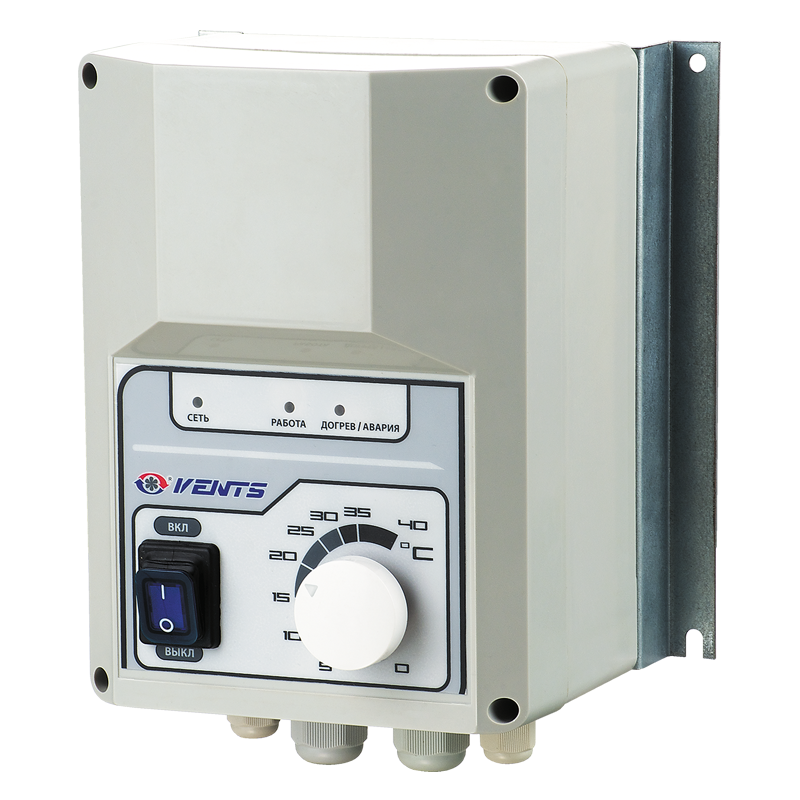
  • Applied in ventilation systems for regulating the power output of electric heaters with load current rating up to 120 A.
  • The controller casing is made of flame-retardant thermoplastic.
  • The controller is equipped with an ON/OFF button and a heating temperature control knob.
  • Electric power output is regulated by proportional connection and disconnection of the full load depending on the pre-set heating temperature.
  • The RNS-16 is capable of controlling only one heating stage.
  • Unlike the smaller models, RNS-25 are capable of controlling one or three heating stages with the power output equal or exceeding that of the controlled stage.
  • The power output of the first stage is controlled steplessly by switching the full load on and off.
  • The second and third stages are controlled in steps.
  • For overheating protection the electric heater must be equipped with two built-in thermal contacts: TK50 with intervention temperature of +50 °C and automatic restarting and ТК90 with response temperature of +90 °С andmanual restarting.
  • The air temperature is set by means of the built-in potentiometer or the external control device generating a 0-10 V control input for increasing the duct temperature proportionally in the range from 0 to +40 °C.
  • The duct temperature sensor must be installed downstream of the heater in the direction of the air stream at the minimum distance of 50 cm from the heater.
  • If the controller runs in the heating power output mode in disregard of the temperature sensor feedback, no duct temperature sensor is necessary whereas the heating power output is regulated in the 0 to 100% range by means of the 0-10 V control signal.
 
PROTECTION
  • Input circuit of the power controller has a thermal fuse for overload protection.
MOUNTING
  • The controller is designed for indoor mounting.
  • Installation shall be performed with respect to the free air circulation for inner circuit cooling.
  • The controller is for vertical installation.
  • Do not install the controller above the heaters and in bad air convection areas.


CONTROL PARAMETERS
 
Regulation time [s] 0,1 (fixed)
Cycle length [s] 1...10 ((adjustable) 
Indication Power, operation and malfunction indicator
Type of temperature sensor used LM 60 
Input signal parameters [V] 0...10 (direct current) 
Set temperature range [°C] 0...40 (adjustable)
Characteristics
Characteristics
Parameter RNS-25
Measurement unit
Frequency Frequency 50 Hz
Max. load current (single stage) Max. load current (single stage) 40 A
Max. load current (three stages) Max. load current (three stages) 120 A
Heater power (single stage) Heater power (single stage) 25 kW
Heater power (three stages) Heater power (three stages) 75 kW
Control circuit supply voltage Control circuit supply voltage 230 V
Cross-section area of screw terminal block input pin Cross-section area of screw terminal block input pin 4...10 mm²
Protection rating IP 54 -
Overall dimensions LxWxH 170х255х140 mm
Mains parameters: Mains parameters: voltage [V]: 210-255, 380-415
frequency [Hz]: 50-60
phases: 1 or 3
-
Operating temperature range Operating temperature range +5...+40 °С
Weight Weight 1.2 kg
Files archieve
Downloads
Select document type
  • Advertising and printing products
  • Certificates
  • Technical documentation
Name
"RNS" product description 06-2015 (pdf 103.97Kb)
Download high quality image "RNS" (psd 2.57Mb)
Download image "RNS" for your website (png 644.19Kb)
"RNS" user's manual 05-2021 (V116-2EN-03) (pdf 847.63Kb)
Dimensions
Characteristics
Parameter Value Measurement unit
Wiring plan
Wiring plan

External connections diagram

Control unit wiring diagrams

Attention!
THE CONTROLLER IS INTENDED FOR VERTICAL MOUNTING ONLY!

Share your opinion

Questionnaire
Basic parameter for domestic fan selection