Login

Privacy Policy (GDPR)
Authorization
Not registered yet? Take advantages of registration:
Products saving in a binding to the projects
Product consultation from our experts - Online
Registration
Signup
By using this form, you confirm that you have read the site terms of use Terms of use and completely accept the terms of use

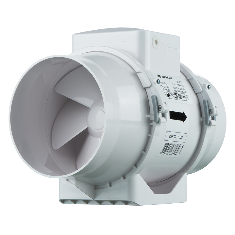
VENTS TT 125


Inline mixed flow fan. Maximum capacity - 280 m3/h.

  • Description
  • Characteristics
  • Downloads
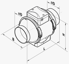
  • Dimensions
  • Additional characteristics
  • Designation key
  • BIM
Description
Description
APPLICATION
  • The VENTS TT fans are featured with wide capabilities and high performance of axial and centrifugal fans and are specifically designed for supply and exhaust ventilation of premises requiring high pressure, powerful air flow and low noise level.
  • The fans are compatible with round air ducts from Ø 100 to 315 mm. Exhaust ventilation systems based on the VENTS TT fans are the best solution for ventilation of bathrooms and kitchens and other humid premises as well for ventilation of flats, cottages, shops, cafes, etc.
DESIGN
  • The casing is made of high-quality durable plastic.
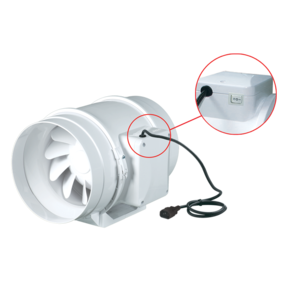
  •  All the models may be equipped with a regulated timer with turn-off delay adjustable from 2 to 30 min.
  • The removable impeller and motor block with a terminal box is fixed to the casing assembled with the spigots by means of special clamps with latches. This makes the fan maintenance fast and easy. The fan maintenance does not require total disassembling. Just pull out the central block from the casing and perform required servicing.
MOTOR
  • The models of VENTS TT series are equipped with a single phase motor and are available in single or two speed modifications. Some dimension types are available with a more powerful motor (VENTS TT…S).
  • The motors have thermal overheating protection to prevent the motor overload.
  • The ball bearings extend the motor service life up to 40 000 hrs. at non-stop operation.
  • The motor has IP X4 ingress protection rating.
SPEED CONTROL
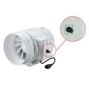
  • The double-speed motors are controlled with a built-in switch (option) or an external switch for multi-speed fans (available upon separate order).
  • An integrated speed controller (option P), an external TRIAC or autotransformer speed controller (available upon separate order) are used for smooth speed control when connected to the maximum speed terminal.
MOUNTING
  • The fans are suitable for mounting at any angle and point of the system. Several fans may be installed inside one system. 
  • Several fans may be installed inside one system:
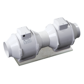
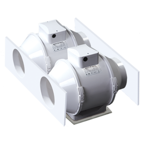
    • parallel mounting to increase air flow;
    • in series mounting to increase operating pressure;
  • The fan case is equipped with a flat mounting plate to attach the fan to the wall.

  • The mounting box may be installed in any position to facilitate mounting and wiring.

THE FAN WITH ELECTRONIC MODULE OF THE TEMPERATURE SENSOR AND SPEED CONTROLLER (U OPTION)
  • The ideal solution for ventilation of the premises with high demands to permanent indoor temperature level, e.g. greenhouses. The fan with the electronic module of the temperature sensor and the speed controller is used for automatic speed control (air capacity regulation) depending on the air temperature in the ventilation duct or inside a room.
  • Two modifications are possible:
    • temperature sensor integrated inside a fan duct (U/U1 option)
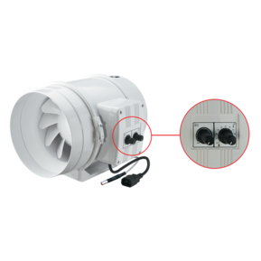
    • external temperature sensor fixed on 4 m power cable (Un / U1n option)
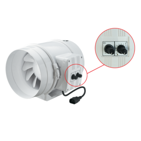
  • The electronic module of the front panel incorporates:
    • the speed control knob for the setting the impeller speed;
    • the thermostat control knob for setting the temperature set point. 
    • thermostat LED light.
OPERATING LOGIC OF THE FAN WITH THE ELECTRONIC MODULE OF THE TEMPERATURE SENSOR AND SPEED CONTROLLER
  • Set the desired air temperature (set point of the thermostat) with the thermostat control knob. Set the required minimum impeller speed (air flow) with the speed control knob. The motor switches to maximum speed (maximum air flow) as the temperature reaches and exceeds the set temperature set point. The motor switches to the pre-set speed as the temperature drops down below the set temperature point.
  • To avoid the frequent motor switching, e.g. when the temperature in the supply air duct is equal to the threshold value, the switching delay time is activated.
There are two switch delay patterns for various cases:
  • The temperature sensor-based switch delay (U option): the motor switches to higher speed as the air temperature exceeds 2°C above the set thermostat set point. The motor revers to the pre-set lower speed as the air temperature drops below the thermostat set point. This pattern is used to keep air temperature to within 2°C. In this case the fan switches are rare.
  • The timer-based switch delay (U1 option): as the air temperature exceeds the set thermostat set point, the motor switches to higher speed and the switch delay timer is activated for 5 min. The motor reverts to lower speed as the air temperature drops down below the thermostat set point and only after the timer countdown.This pattern is used for exact air temperature control. The fan changes its speed more often as compared to the temperature sensor-based switch delay, however the minimum timer interval is 5 minutes.
TT FANS APPLICATIONS

 
bathroom ventilation example office ventilation example
parallel installation of fans in the storehouse to increase the air capacity
Characteristics
Characteristics
Parameter TT 125
min
TT 125
max
Measurement unit
Voltage 1~230 1~230 V
Frequency 50/60 50/60 Hz
Current 0.18 0.27 A
Sound pressure level at 3 m distance 28 37 dBА
Power consumption 23 37 W
Maximum air capacity 220 280 m³/h
Max. transported air temperature 60 60 °С
RPM 1950 2455 min-1
Protection rating IP X4 IP X4 -
Design mixed-flow mixed-flow -
Weight 1.35 1.35 kg
Duct diameter 100 315 mm
Casing material plastic plastic -
SEC Class B B -
Sound-insulated casing yes yes -
Duct for round air ducts for round air ducts -
Mounting Inline Inline -
* To meet the requirements of ErP 2018, a speed controller and local demand control typology must be applied (connect a sensor). To meet the requirements of ErP 2018, a speed controller and local demand control typology must be applied (connect a sensor). -
Files archieve
Downloads
Select document type
  • Advertising and printing products
  • Certificates
  • Technical documentation
Name
"VENTS TT" user's manual 10-2022 (V10EN-12) (pdf 936.28Kb)
Download high quality image "VENTS TT (ErP 2018)" (psd 3.99Mb)
Declaration of сonformity "TT" (pdf 1.63Mb)
Download image "VENTS TT (ErP 2018)" for your website (png 301.04Kb)
RFA models "VENTS TT" (rfa 376Kb)
DWG models "VENTS TT" (rar 331.41Kb)
Download high quality image "VENTS TT 100" (psd 74.82Kb)
Download high quality image "VENTS TT 125" (psd 2.07Mb)
Download high quality image "VENTS TT 150" (psd 2.29Mb)
Download high quality image "VENTS TT 160" (psd 2.22Mb)
Download image "VENTS TT 100" for your website (png 522.39Kb)
Download image "VENTS TT 125" for your website (png 502.95Kb)
Download image "VENTS TT 150" for your website (png 565.64Kb)
Download image "VENTS TT 160" for your website (png 550.7Kb)
"VENTS TT" product description 05-2022 (pdf 1.74Mb)
Dimensions
Characteristics
VENTS TT 125
Parameter Value Measurement unit
∅D 123 mm
B 167 mm
H 190 mm
L 246 mm
Additional characteristics
Sound power level, A-filter applied Sound pressure level at 3 meters, A-filter applied Sound pressure level at 1 meters, A-filter applied
  Gen. Octave-frequency band [Hz]
  Hz 63 125 250 500 1000 2000 4000 8000 LpA, 3 m [dBA] LpA, 1 m [dBA]
 Min speed
LwA to inlet dBA 53 17 30 48 48 48 43 35 22 33 43
LwA to outlet dBA 52 16 29 47 47 47 43 34 21 32 42
LwA to environment dBA 49 13 26 43 44 44 40 32 20 28 38
 
 Max speed
LwA to inlet dBA 62 28 38 57 58 57 52 43 29 42 52
LwA to outlet dBA 61 27 37 55 57 56 51 42 29 41 51
LwA to environment dBA 58 23 33 51 53 52 48 40 27 37 47
Designation key
Designation key
Series Air duct diameter Options
VENTS TT 100; 125; 150; 160 S: high-powered motor;
Т: adjustable timer from 2 to 30 minutes;
U: speed controller with an electronic thermostat and a temperature sensor integrated inside an air duct. Temperature-based operation logic;
Un: speed controller with an electronic thermostat and a temperature sensor fixed on a 4 m cable. Temperature-based operation logic;
U1: speed controller with an electronic thermostat and a temperature sensor integrated inside an air duct. Timer-based operation logic;
U1n: speed controller with an electronic thermostat and a temperature sensor fixed on a 4 m cable. Timer-based operation logic;
U2n: speed controller with an electronic thermostat and a temperature sensor fixed on a 4 m cable. Temperature-based switching on/off;
R1: power cord with mains plug;
V:
threeposition speed switch;
P:
integrated smooth speed controller.
BIM
BIM

Share your opinion

Questionnaire
Where have you learned about us?