

 Domestic fans
  Industrial and commercial fans
  Single-room ventilation systems with heat recovery
  Air handling units
  Air heating systems
  Smoke extraction and ventilation
  Accessories for ventilating systems
  Electrical accessories
  Ventilation ducts and fittings
  Air distribution components
  Ventilation kits and vents
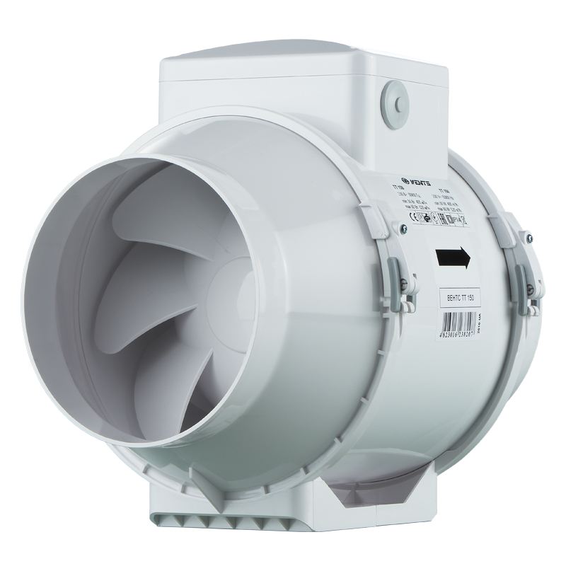
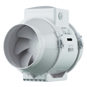
 VENTS TT 150

- Description
- Characteristics
- Downloads
- Dimensions
- Additional characteristics
- Designation key
- BIM
Description
Description
| APPLICATION | |
|
|
| DESIGN | |
|
|
 |
|
|
|
| MOTOR | |
|
|
 |
|
| SPEED CONTROL | |
|
|
| MOUNTING | |
|
|
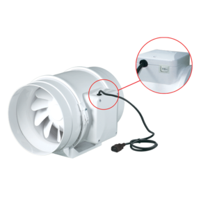
| THE FAN WITH ELECTRONIC MODULE OF THE TEMPERATURE SENSOR AND SPEED CONTROLLER (U OPTION) | |
|
|
| OPERATING LOGIC OF THE FAN WITH THE ELECTRONIC MODULE OF THE TEMPERATURE SENSOR AND SPEED CONTROLLER | |
|
|
| There are two switch delay patterns for various cases: | |
|
|
| TT FANS APPLICATIONS | |
|
|
 |
| bathroom ventilation example | office ventilation example |
 |
|
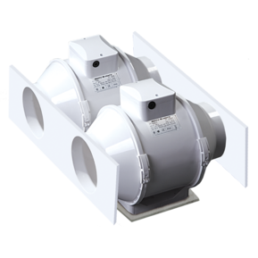
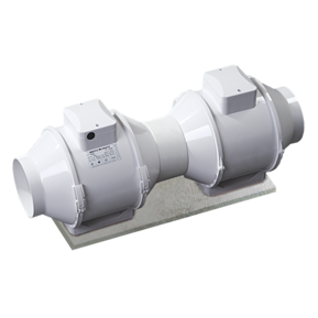
| parallel installation of fans in the storehouse to increase the air capacity | |

Characteristics
Characteristics
| Parameter |
TT 150 min |
TT 150 max |
Measurement unit |
|---|---|---|---|
| Voltage | 1~230 | 1~230 | V |
| Frequency | 50/60 | 50/60 | Hz |
| Sound pressure level at 3 m distance | 33 | 44 | dBА |
| Power consumption | 29 | 60 | W |
| Maximum air capacity | 405 | 520 | m³/h |
| Current | 0.17 | 0.27 | A |
| RPM | 1680 | 2460 | min-1 |
| Max. transported air temperature | 60 | 60 | °С |
| Protection rating | IP X4 | IP X4 | - |
| Design | mixed-flow | mixed-flow | - |
| Weight | 2.65 | 2.65 | kg |
| Duct diameter | 150 | 150 | mm |
| Casing material | plastic | plastic | - |
| SEC Class | B | B | - |
| Duct | for round air ducts | for round air ducts | - |
| Mounting | Inline | Inline | - |
| * | To meet the requirements of ErP 2018, a speed controller and local demand control typology must be applied (connect a sensor). | To meet the requirements of ErP 2018, a speed controller and local demand control typology must be applied (connect a sensor). | - |
Files archieve
Downloads
Select document type
Dimensions
Characteristics
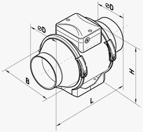
| Parameter | Value | Measurement unit |
|---|---|---|
| ∅D | 146 | mm |
| B | 223 | mm |
| H | 250 | mm |
| L | 295 | mm |
Additional characteristics
Additional characteristics
| Sound power level, A-filter applied | Sound pressure level at 3 meters, A-filter applied | Sound pressure level at 1 meters, A-filter applied | ||||||||||
| Gen. | Octave-frequency band [Hz] | |||||||||||
| Hz | 63 | 125 | 250 | 500 | 1000 | 2000 | 4000 | 8000 | LpA, 3 m [dBA] | LpA, 1 m [dBA] | ||
| Min speed | ||||||||||||
| LwA to inlet | dBA | 66 | 35 | 46 | 63 | 60 | 57 | 53 | 43 | 28 | 45 | 55 |
| LwA to outlet | dBA | 65 | 34 | 45 | 62 | 59 | 56 | 53 | 43 | 28 | 44 | 54 |
| LwA to environment | dBA | 54 | 24 | 35 | 50 | 49 | 47 | 44 | 36 | 23 | 34 | 44 |
| Max speed | ||||||||||||
| LwA to inlet | dBA | 75 | 42 | 52 | 71 | 69 | 67 | 64 | 56 | 43 | 54 | 64 |
| LwA to outlet | dBA | 74 | 41 | 50 | 70 | 69 | 66 | 63 | 56 | 42 | 53 | 63 |
| LwA to environment | dBA | 64 | 32 | 41 | 59 | 58 | 57 | 54 | 48 | 36 | 43 | 53 |
Designation key
Designation key
| Series | Air duct diameter | Options |
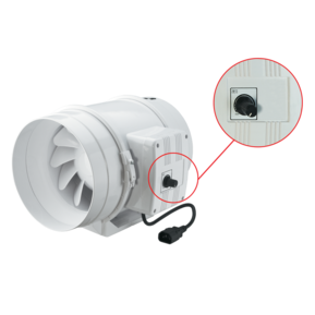
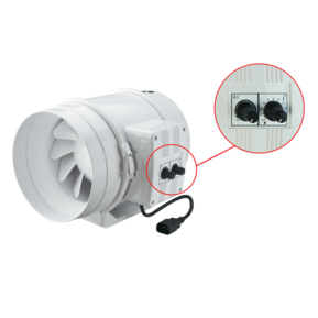
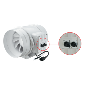
| VENTS TT | 100; 125; 150; 160 | S: high-powered motor; Т: adjustable timer from 2 to 30 minutes; U: speed controller with an electronic thermostat and a temperature sensor integrated inside an air duct. Temperature-based operation logic; Un: speed controller with an electronic thermostat and a temperature sensor fixed on a 4 m cable. Temperature-based operation logic; U1: speed controller with an electronic thermostat and a temperature sensor integrated inside an air duct. Timer-based operation logic; U1n: speed controller with an electronic thermostat and a temperature sensor fixed on a 4 m cable. Timer-based operation logic; U2n: speed controller with an electronic thermostat and a temperature sensor fixed on a 4 m cable. Temperature-based switching on/off; R1: power cord with mains plug; V: threeposition speed switch; P: integrated smooth speed controller. |
BIM
BIM

