Domestic fans
  Industrial and commercial fans
  Single-room ventilation systems with heat recovery
  Air handling units
  Air heating systems
  Smoke extraction and ventilation
  Accessories for ventilating systems
  Electrical accessories
  Ventilation ducts and fittings
  Air distribution components
  Ventilation kits and vents
 VENTS VNV-1A 80 KVK

- Description
- Characteristics
- Capacity diagram
- Downloads
- Dimensions
- Additional characteristics
- Dimensions
- Options description
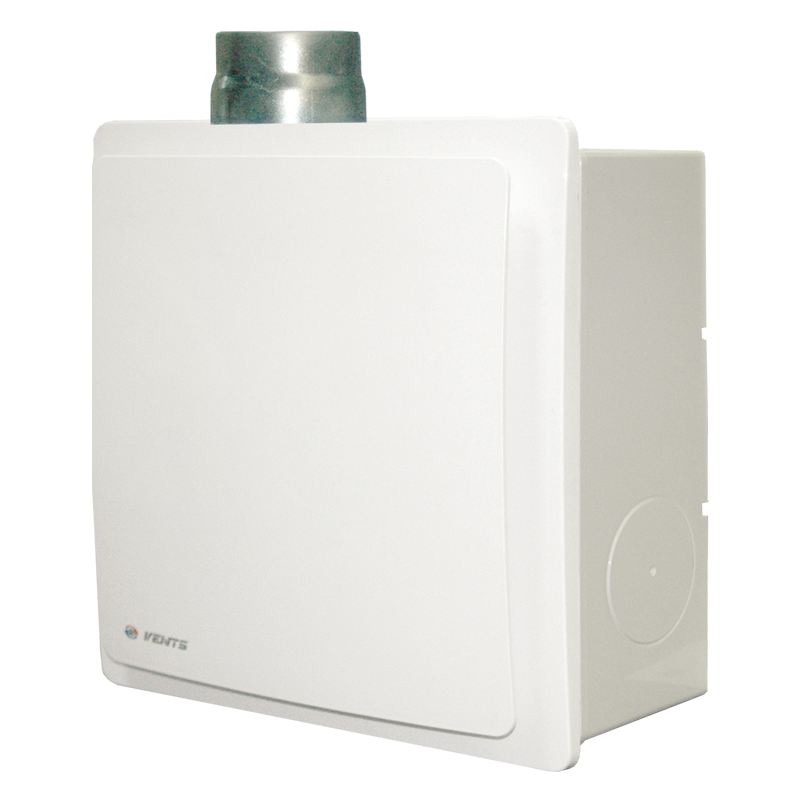
Description
Description
| APPLICATION | |
|
|
| DESIGN | |
|
|
| MOTOR | |
|
|
| MODIFICATIONS AND OPTIONS | |
| VNV-1A(E) 80 KVK T — the fan is equipped with a timer and a fire-resisting damper. VNV-1A(E) 80 KVK TR — the fan is equipped with an adjustable timer and a fire-resisting damper. |
VNV-1A(E) 80 KVK I — the fan is equipped with an interval switch and a fire-resisting damper. VNV-1A(E) 80 KVK H — the fan is equipped with a humidity sensor and a fire-resisting damper. |
|
|
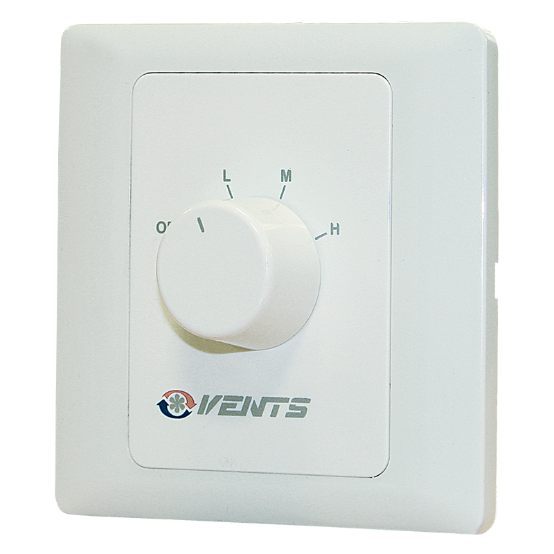
| CONTROL | |
|
|
| MOUNTING EXAMPLE | |
 |
|
|
|
Characteristics
Characteristics
| Parameter |
VENTS VNV-1A 80 KVK speed 1 |
VENTS VNV-1A 80 KVK speed 2 |
Measurement unit |
|---|---|---|---|
| Engine Type | 220В / 50Гц | 220В / 50Гц | - |
| Voltage | 220-240 | 220-240 | V |
| Frequency | 50 | 50 | Hz |
| Power consumption | 12 | 17 | W |
| Air capacity | 35 | 63 | m³/h |
| Current | 0.12 | 0.14 | A |
| RPM | 890 | 1350 | min-1 |
| Sound pressure level at 3 m | 26.6 | 30 | dBА |
| Maximum transported air temperature | 50 | 50 | °С |
Electric connection  |
3×1.5 | 3×1.5 | mm² |
| Spigot size | 80 | 80 | mm |
| Design | centrifugal | centrifugal | - |
| Duct diameter | 80 | 80 | mm |
| IP Code | IP 55 | IP 55 | - |
| Type | exhaust | exhaust | - |
| Mounting | wall mounting, ceiling mounting | wall mounting, ceiling mounting | - |
Capacity diagram
Capacity diagram
- Selection method:
- Air flow:
- Pressure:
Operating point
- Air flow: --
- Pressure: ---
Files archieve
Downloads
Select document type
Dimensions
Characteristics
| Parameter | Value | Measurement unit |
|---|
Additional characteristics
Additional characteristics

Dimensions
Dimensions

Options description
Options description
| Name | Description |
| T timer modification |
The fan is switched on to the maximum speed manually with the external switch, turn-on delay time is 50 seconds. The return to default position is performed with the timer, run-out time is 6 minutes. Continuous low speed operation is possible. |
| TR adjustable timer modification |
The fan can be switched to the maximum speed manually with the external switch. Turn-on delay time is set with the internal regulator ranging from 0 to 150 seconds. Run-out time is set with the internal regulator from 2 to 30 minutes. Continuous low speed operation is possible. |
| I interval switch modification |
The fan switches periodically to the maximum speed while operation. The switching interval is set by means of the internal regulator ranging between 0.5 and 15 hours. Run-out time is 10 minutes. The fan can be switched manually with the external switch, turn-on delay time is 50 seconds. Continuous low speed operation is possible. |
| H humidity sensor modification |
The fan switches to the maximum speed as relative humidity level in the room increases. It switches off as relative humidity level drops by 10 % below the set level. The humidity threshold is adjusted in the range between 60 % and 90 %. Force switching to the maximum speed is provided, in this case the turn-on delay time is 50 seconds, and the run-out time is set by the internal regulator between 2 and 30 minutes. Continuous low speed operation is possible. |