

 Domestic fans
  Industrial and commercial fans
  Single-room ventilation systems with heat recovery
  Air handling units
  Air heating systems
  Smoke extraction and ventilation
  Accessories for ventilating systems
  Electrical accessories
  Ventilation ducts and fittings
  Air distribution components
  Ventilation kits and vents
 VENTS Polyvent 665-Comby series
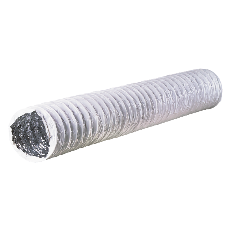
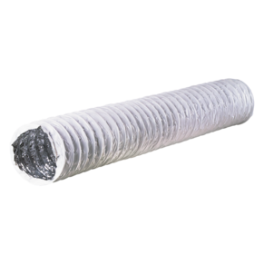

Flexible non-insulated air ducts with steel wire frame covered with aluminium foil and polyether
Model features


- Description
- Modifications
- Downloads
- Colour range
- Packing
- Order code
- Accessories
- Pressure loss diagram
- Calculation example
Description
Description
DESCRIPTION
|
FEATURES
Versus PVC foil air ducts:
Versus aluminium foil air ducts:
|
Modifications
Downloads
Downloads
Select document type
Colour range
Colour range
 |
| White |
| (_) |
Packing
Packing
 |
 |
 |
||
| Cardboard box | Unit coloured packing | Net |
Order code
Order code
| Polyvent 665 – Comby | fire safety class | Ø | / | length | ||
| M0 | ||||||
| M1 | ||||||
Accessories
Accessories


Pressure loss diagram
Pressure loss diagram
PRESSURE LOSS DIAGRAM PER 1 M STRETCHED AIR DUCT

Calculation example
Calculation example
 |
|
