| PURPOSE |
|
- The fans are used for extraction of smoke in case of fire and removal of hot air outside.
|
- The fans are also used for general ventilation systems.
|
| OPERATION |
|
- The fans are rated for permanent operation at ambient air temperatures from -60 °C up to +50 °C (depends on climatic category, see the Designation key).
- The fans are able to operate 2 hours at the temperatures +300 °C and +400 °C.
|
- The fans with a fire resistance class of 200 °C/2 hours can be produced on request.
- The characteristics of the 200 °C/2 hours fans are completely identical to 300 °C/2 hours fans.
|
| DESIGN |
|
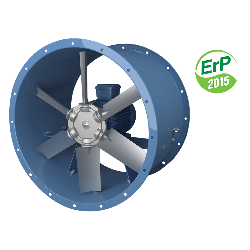
- The fan consists of a casing, an impeller and a motor.
- The metal casing with rolled flanges helps achieve outstanding rigidity and minimum clearances between the casing and the blades.
- There is an inspection hatch in the casing for easy maintenance.
|
- All the casing components are powder coated for improved protection against the environmental effects.
- The weight of the fans may differ from the one stated in the catalogue and depends on the components used (motor, terminal box, etc.).
|
| MOTOR |
|
- The fans are equipped with three-phase (400 V/50 Hz) motors.
- Motor ingress protection rating is IP55.
- Depending on the model, the fans have single- or double-speed modifications.
|
- The single-speed models are equipped with 2-, 4- or 6-pole motors.
- The double-speed models are equipped with 2/4-, 4/6- or 4/8-pole motors.
|
| IMPELLER |
|
- Depending on the size and the required air capacity the fans are equipped with impellers with 4, 5, 6, 7, 8, 9 or 12 blades angled from 20° to 50° to ensure precise matching of fans with the operating point.
- The specially designed impeller blades ensure high efficiency of the fan while keeping noise well under control.
|
- The impellers are dynamically balanced.
- Low weight and low moment of the impeller inertia help reduce the fan start-up time.
- The fan blades are made of cast aluminium.
|
| MOUNTING |
|
- The fans can be mounted on any flat surface or directly into a ventilation duct.
- The units are suitable for both horizontal and vertical configurations.
|
- Installation in the air duct requires flanges to attach the fan to the ductwork.
- To attach the fan to the floor, the wall or the ceiling use the O-VO carriers (not included as standard, should be purchased separately).
|
|
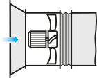
Fan installation with no upstream ducting
- Axial fans without upstream ducting must be equipped with the VK-VO inlet cone to improve the air flow parameters.
|
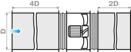
Fan installation into an air duct system:
- To ensure a uniform air flow the fan should be preceded by a straight duct section with a cross-section area equal to half of that of the fan.
- The length of the duct section should be 3 ÷ 4 D (D is the inner diameter of the fan).
- The length of the straight duct section downstream of the fan should be 1.5 ÷ 2 D.
- Reduction of the recommended duct length values results in a drop of the fan pressure and performance.
- To reduce noise and vibration use the VVGF flexible joints.
|
|
Fan installation with no downstream ducting:
- If the axial fan is a terminal device of the ventilation system (i.e. there is no downstream ducting) the unit must be equipped with a diffuser to reduce the air flow velocity and the fan dynamic pressure.
- Reduction of the air discharge velocity results in a significant reduction of shock losses which are proportional to the square of velocity decrement.
- The fan should not be equipped with a downstream contractor.

|
|
Installation near bends:
- To install the fan directly downstream of a bend (elbow) use a curved section with a large bending radius or an array of internal guide vanes.

|
|
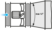
Changing diameter installation:
When changing from a smaller diameter to a larger one use a connector diffuser with the maximum opening angle of 12°.
|
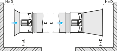
Obstructed space installation:
- To ensure normal operation of the fan in an obstructed space make sure to provide for a sufficient distance between the inlet and outlet flanges and the floor, walls, bulky equipment and obstacles.
|
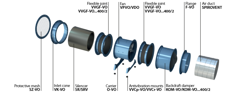
| COMPLETE SOLUTIONS FOR AXIAL FANS |
 |
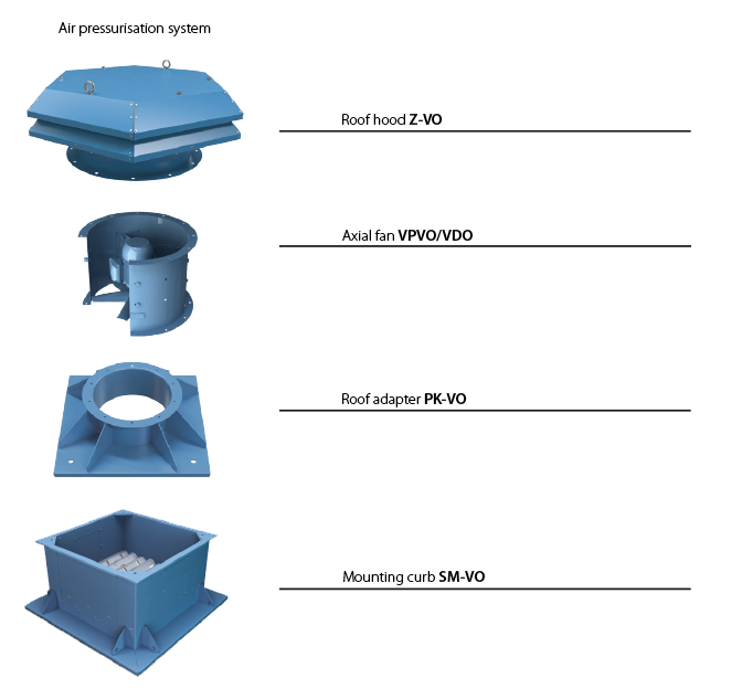
| INSTALLATION EXAMPLE OF AXIAL FANS ON ROOFTOP |
 |


 Domestic fans
  Industrial and commercial fans
  Single-room ventilation systems with heat recovery
  Air handling units
  Air heating systems
  Smoke extraction and ventilation
  Accessories for ventilating systems
  Electrical accessories
  Ventilation ducts and fittings
  Air distribution components
  Ventilation kits and vents


