

 Domestic fans
  Industrial and commercial fans
  Single-room ventilation systems with heat recovery
  Air handling units
  Air heating systems
  Smoke extraction and ventilation
  Accessories for ventilating systems
  Electrical accessories
  Ventilation ducts and fittings
  Air distribution components
  Ventilation kits and vents
 VENTS 100 MF Duo

- Description
- Characteristics
- Capacity diagram
- Downloads
- Modifications
- Dimensions
- Designation key
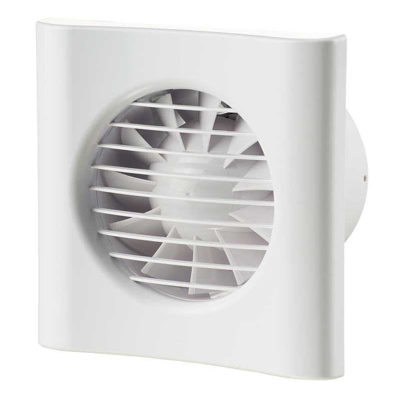
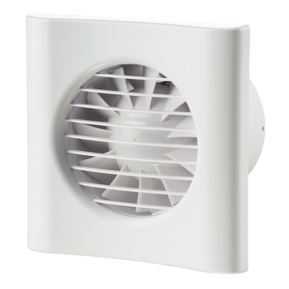
Description
Description
| APPLICATIONS | |
|
|
| DESIGN | |
|
|
| MOTOR | |
|
|
| CONTROL | |
|
Manual control:
|
|
|
Automatic:
|
|
| MOUNTING FEATURES | |
|
|
| MOUNTING EXAMPLE | |
 |
|
Characteristics
Characteristics
| Parameter |
VENTS 100 MF Duo min |
VENTS 100 MF L Duo min |
VENTS 100 MF T1 Duo min |
VENTS 100 MF TH Duo min |
VENTS 100 MF Duo max |
VENTS 100 MF L Duo max |
VENTS 100 MF T1 Duo max |
VENTS 100 MF TH Duo max |
Measurement unit |
|---|---|---|---|---|---|---|---|---|---|
| Speed | min | min | min | min | max | max | max | max | - |
| Voltage | 220-240 | 220-240 | 220-240 | 220-240 | 220-240 | 220-240 | 220-240 | 220-240 | V |
| Frequency | 50 | 50 | 50 | 50 | 50 | 50 | 50 | 50 | Hz |
| Power consumption | 5 | 5 | 5 | 5 | 8 | 8 | 8 | 8 | W |
| Air capacity | 54 | 54 | 54 | 54 | 81 | 81 | 81 | 81 | m³/h |
| RPM | 1800 | 1800 | 1800 | 1800 | 2100 | 2100 | 2100 | 2100 | min-1 |
| Current | 0.030 | 0.030 | 0.030 | 0.030 | 0.050 | 0.050 | 0.050 | 0.050 | A |
| Sound pressure level at 3 m | 23 | 23 | 23 | 23 | 28 | 28 | 28 | 28 | dBА |
| Weight | 0.55 | 0.55 | 0.55 | 0.55 | 0.55 | 0.55 | 0.55 | 0.55 | kg |
| Design | axial | axial | axial | axial | axial | axial | axial | axial | - |
| Duct diameter | 100 | 100 | 100 | 100 | 100 | 100 | 100 | 100 | mm |
| IP Code | IP 44 | IP 44 | IP 44 | IP 44 | IP 44 | IP 44 | IP 44 | IP 44 | - |
| Mounting | wall mounting, ceiling mounting | wall mounting, ceiling mounting | wall mounting, ceiling mounting | wall mounting, ceiling mounting | wall mounting, ceiling mounting | wall mounting, ceiling mounting | wall mounting, ceiling mounting | wall mounting, ceiling mounting | - |
Capacity diagram
Capacity diagram
- Selection method:
- Air flow:
- Pressure:
Operating point
- Air flow: --
- Pressure: ---
Files archieve
Downloads
Select document type
Modifications
| Modification name |
|---|
| VENTS 100 MF Duo |
| VENTS 100 MF L Duo |
| VENTS 100 MF T1 Duo |
| VENTS 100 MF TH Duo |
| Modification name | Humidity sensor | Timer | Pull-cord switch | Ball bearing motor | No extra functions |
|---|---|---|---|---|---|
| VENTS 100 MF Duo | - | - | - | - |
|
| VENTS 100 MF L Duo | - | - | - |

|
- |
| VENTS 100 MF T1 Duo | - |

|
- | - | - |
| VENTS 100 MF TH Duo |

|
|
- | - | - |
|
|
|
|
|
|
|
|
Dimensions
Characteristics

| Parameter | Value | Measurement unit |
|---|---|---|
| ∅D | 99 | mm |
| B | 150 | mm |
| L | 79 | mm |
| L1 | 19 | mm |
Designation key
Designation key
| PICTURE SYMBOL | DESIGNATION | MODIFICATION DESCRIPTION |
 |
MF L Duo | The motor is equipped with ball bearings to increase the service life (about 40 thousand operating hours) and fan mounting at any angle. The bearings are maintenance-free and contain enough grease for the entire operating period. |
 |
MF T1 Duo | Equipped with an adjustable high-speed turn-on delay timer (from 0 to 2 minutes) and an adjustable high-speed turn-off delay timer (from 2 to 30 minutes). |
 |
MF TH Duo | Equipped with an adjustable turn-off delay timer (from 2 to 30 minutes) and a fixed turn-on delay timer (45 s) with a humidity sensor adjustable from 60 % to 90 %. |
Similar products


