Login

Privacy Policy (GDPR)
Authorization
Not registered yet? Take advantages of registration:
Products saving in a binding to the projects
Product consultation from our experts - Online
Registration
Signup
By using this form, you confirm that you have read the site terms of use Terms of use and completely accept the terms of use

MICRA 80 A3

MICRA 80 A3
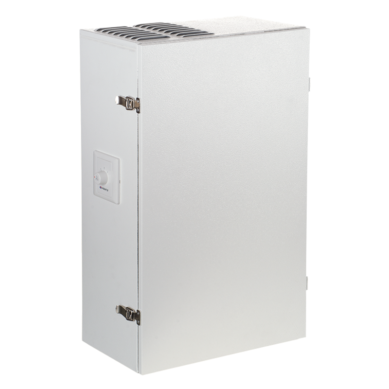
MICRA 80 A3 is a single-room air handling unit for balanced energy saving ventilation of flats, cottages, social and commercial premises. No need to connect air ducts. This unit is ideally suited for creating simple yet highly efficient ventilation systems in newly erected and renovated spaces.
Model features
  • Multiple modes
  • ЕС-Motor
  • Single-room air handling units with heat recovery
  • Description
  • Modifications
  • Downloads
  • Accessories
  • Ventilation system arrangement
Description
Description
FEATURES  
  • Efficient supply and exhaust ventilation of separate premises (rooms).
  • Enthalpy cross-flow heat exchanger with heat recovery efficiency from 68 % up to 77 %.
  • Centrifugal fans with forward curved blades.
  • Asynchronous motors with ball bearings. Integrated control system with three operation modes and air flow range from 40 up to 80 m³/h.
  • Silent operation (24/32/41 dBA).
  • Air filtration with two integrated G4 filters.
  • Easy installation.
  • Suitable for continuous operation.
OPERATING LOGIC  
  • Fresh intake air from outside moves through the filter and the heat exchanger and is delivered to the premise with the supply fan.
  • Warm stale air moves from the room through the filter and the heat exchanger and then is exhausted outside with the exhaust fan.
  • Heat energy of warm extract air is transferred to clean intake air and warms it up.
  • Heat recovery minimizes thermal energy losses and space heating expenses in cold seasons.
  • Intake and extract air flows are fully separated within the heat exchangers and pollutants, odours and microbes contained in extract air are not transmitted to supply air.
CONTROL AND AUTOMATION  
  • The unit is operated with a three-position speed switch.
  • The control system enables three operation modes:
  1. Supply and exhaust ventilation with minimum air flow rate of 40 m³/h and noise level of 24 dBA.
  2. Supply and exhaust ventilation with medium air flow rate of 60 m³/h and noise level of 32 dBA.
  3. Supply and exhaust ventilation with maximum air flow rate of 80 m³/h and noise level of 41 dBA.
А3: three-position speed switch (P3-1-300)
Modifications
Modification name
+
Downloads
Downloads
Select document type
  • Advertising and printing products
  • Certificates
  • Technical documentation
Name
Сatalogue "Single-room air handling units with heat recovery MICRA" (pdf 6.4Mb)
"VENTS MICRA 80 A3" product description 05-2020 (pdf 1.68Mb)
"VENTS MICRA 80 A3/A4" user's manual 04-2017 (V104EN-02) (pdf 3.32Mb)
Download high quality image "VENTS MICRA 80 A3" (psd 1.95Mb)
Download image "VENTS MICRA 80 A3" for your website (png 448.69Kb)
Accessories
Accessories
   
Round Ø 125 mm telescopic air duct, adjustable length from 500 up to 1000 mm   MVM 122 bVs N stainless steel outer hood   SF 195х195х6 G4 filter
Ventilation system arrangement
  • One MICRA 80 A3 air handling unit should be installed in each space requiring ventilation.
  • A single unit is capable of ensuring efficient ventilation in spaces with floor area up to 32 m².
  • A ventilation system based on MICRA 80 A3 is able to provide continuous air exchange and save heat in winter and cool in summer.
  • Mark the holes for the air ducts on the wall with the supplied cardboard master plate. After drilling the holes fix the master plate to the wall with a mounting tape. Insert the 125 mm plastic air ducts in the core holes.
  • The master plate is used to place the air ducts in a required position and to align the unit spigots with the air ducts.
  • Install the outdoor ventilation hoods from outside to prevent ingress of water and foreign objects inside the unit.
  • Install the air ducts slightly sloped down to outside to ensure condensate drainage from the unit.
  • After the air ducts are fixed in required position using the outer ventilation hoods and the master plate fill the gaps between the air ducts and the wall with a mounting foam through the special slots in the master plate.
  • After the mounting foam hardens, remove the master plate and cut protruding parts of the air ducts to be flush with wall surface.
  • To mount the unit casing, open the service panel and take off the heat exchanger.
  • Connect the unit spigots to the plastic air ducts and fix the unit casing to the wall with screws and dowels.
  • After completion of the casing mounting and wiring operations re-install the heat exchanger and the front panel.
Share your opinion

Questionnaire
Basic parameter for domestic fan selection