Domestic fans
  Industrial and commercial fans
  Single-room ventilation systems with heat recovery
  Air handling units
  Air heating systems
  Smoke extraction and ventilation
  Accessories for ventilating systems
  Electrical accessories
  Ventilation ducts and fittings
  Air distribution components
  Ventilation kits and vents
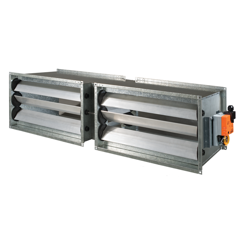
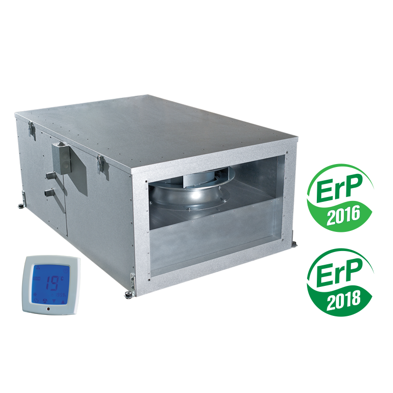
 VENTS PA 03 W4


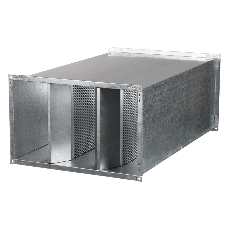
Suspended air supply unit with the air flow up to 3260 m³/h in the sound- and heat-insulated casing with the water heater
- Description
- Characteristics
- Capacity diagram
- Downloads
- Dimensions
- Additional characteristics
- Hot water coil parameters
- Designation key
- Accessories
Description
Description
| DESCRIPTION | CASING |
|
|
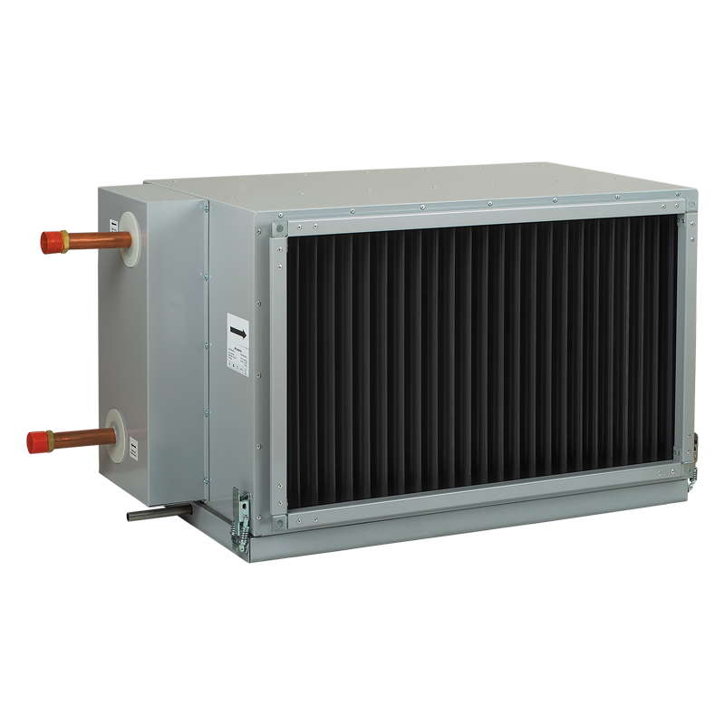
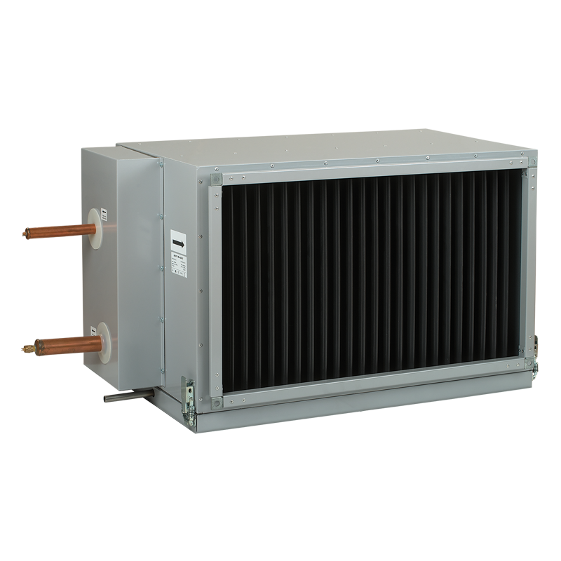
| FILTER | HEATER |
|
|
| FAN | |
|
|
| MOUNTING | |
|
|
| CONTROL AND AUTOMATION | |
|
|
| CONTROL AND PROTECTION FUNCTIONS | |
|
|
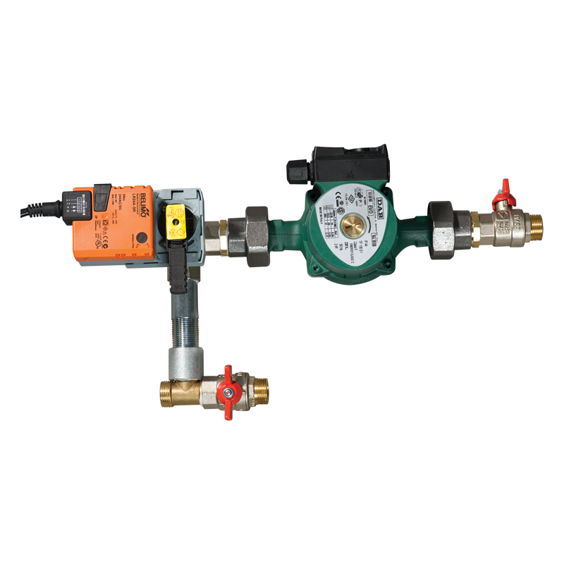
| SUPPLEMENTARY EQUIPMENT | |
|
|
Characteristics
Characteristics
| Parameter |
PA 03 W4 |
Measurement unit |
|---|---|---|
| Frequency | 50 | Hz |
| Phase | 3 | ˜ |
| Voltage | 400 | V |
| Fan current | 2.4 | A |
| Maximum fan power | 1330 | W |
| Air capacity | 3260 | m³/h |
| Total unit power | 1330 | W |
| Total unit current | 2.4 | A |
| RPM | 2730 | min-1 |
| Filter | G4 (F7) pocket type* | - |
| Transported air temperature | -25 ... +40 | °С |
| Sound pressure level at 3 m distance | 57 | dBА |
| Casing material | aluzinc | - |
| Heating | water heating | - |
| Insulation | 50 mm mineral wool | - |
| Connected air duct size | 600х350 | mm |
| Number of water (glycol) coil rows | 4 | - |
| Width | 600 | mm |
| Weight | 94 | kg |
| Height | 350 | mm |
| Duct | for rectangular air ducts | - |
| * | option | - |
Capacity diagram
Capacity diagram
- Selection method:
- Air flow:
- Pressure:
Operating point
- Air flow: --
- Pressure: ---
Files archieve
Downloads
Select document type
"Control and automation block for VENTS PA...W" user's manual 06-2018 (V43(automatic)EN-06) (pdf 1.61Mb)
"Control system for air supply and air handling units based on Freemax controllers and AC208A2 sensor control panels" user's manual 07-2023 (V99EN-03) (pdf 7.14Mb)
Dimensions
Characteristics

| Parameter | Value | Measurement unit |
|---|---|---|
| B | 600 | mm |
| B1 | 620 | mm |
| B2 | 787 | mm |
| B3 | 744 | mm |
| H | 350 | mm |
| H1 | 370 | mm |
| H2 | 500 | mm |
| L | 1252 | mm |
| L1 | 1212 | mm |
Additional characteristics
Additional characteristics
| Sound-power level | Gen | Octave-frequency band [Hz] | ||||||||
| 63 | 125 | 250 | 500 | 1000 | 2000 | 4000 | 8000 | |||
| LWA to inlet | dBA | 71 | 57 | 71 | 66 | 57 | 51 | 50 | 56 | 56 |
| LWA to outlet | dBA | 78 | 57 | 70 | 73 | 73 | 70 | 67 | 64 | 53 |
| LWA to environment | dBA | 59 | 39 | 58 | 62 | 51 | 44 | 52 | 49 | 46 |
Hot water coil parameters
Hot water coil parameters

How to use water heater diagrams
System Parameters: Air flow = 2700 m³/h. Outside air temperature = -25 °C. Water temperature (in/out) = 70/50 °C.
- Air Speed. Starting from 2700 m³/h on the air flow scale draw a vertical line ① till the air speed axis which makes about 3.59 m/s.
- Supply air temperature. Prolong the line ① up to the point where it crosses the outside air temperature (blue curve, e.g. -25 °C); then draw a horizontal line ② from this point to the left till crossing water in/out temperature curve (e.g. 70/50 °C). From this point draw a vertical line ③ to the supply air temperature axis on top of the graphic (+28 °C).
- Heating coil capacity. Prolong the line ① up to the point where it crosses the outside air temperature (e.g. -25 °C, red curve) and draw a horizontal line ④ from this point to the right until it crosses water in/out temperature curve (e.g. 70/50 °C), from here draw a vertical line ⑤ up to the scale representing the heating coil capacity (58.0 kW).
- Water flow. Prolong the line ⑤ down to water flow axis at the bottom of the graphic ⑥ (0.73 l/s).
- Water pressure drop. Draw the line ⑦ from the point where the line ⑥ crosses the black curve to the pressure drop axis (14.0 kPa).
Designation key
Designation key
| Series | Unit standard size | Heater type | Row number of the heater | Integrated control system |
| VENTS PA | 01; 02; 03; 04 | W: water | 2: two rows; 3: three rows; 4: four rows |
LCD: integrated automation with A13 control panel |
Accessories
Accessories
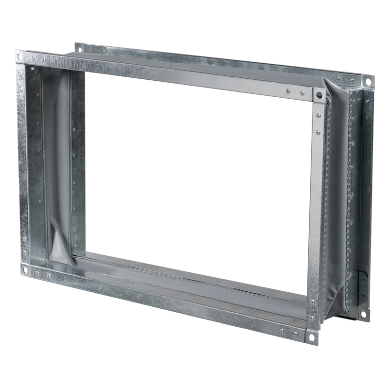
| Type | G4 replaceable filter | F7 replaceable filter | Filter type |
| PA 01 W2 | SFK 474x269x27 G4 | SFK 474x269x27 F7 | pocket filter |
| PA 01 W4 | |||
| PA 02 W2 | SFK 538x342x27 G4 | SFK 538x342x27 F7 | pocket filter |
| PA 02 W4 | |||
| PA 03 W2 | SFK 637x395x27 G4 | SFK 637x395x27 F7 | pocket filter |
| PA 03 W4 | |||
| PA 04 W2 | SFK 737x441x27 G4 | SFK 737x441x27 F7 | pocket filter |
| PA 04 W3 |
Accessories
Similar products