Domestic fans
  Industrial and commercial fans
  Single-room ventilation systems with heat recovery
  Air handling units
  Air heating systems
  Smoke extraction and ventilation
  Accessories for ventilating systems
  Electrical accessories
  Ventilation ducts and fittings
  Air distribution components
  Ventilation kits and vents
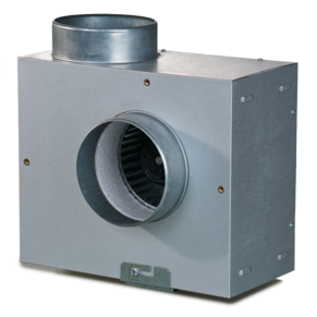
 VENTS KSA series


- Description
- Modifications
- Downloads
- Designation key
| APPLICATIONS | |
|
|
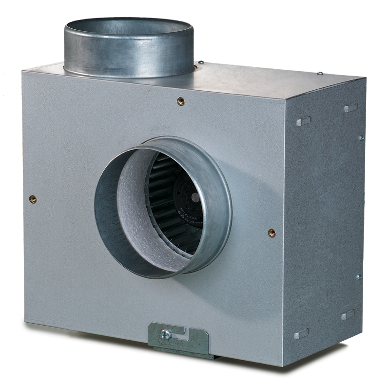
| DESIGN | |
|
|
| MOTOR | |
|
|
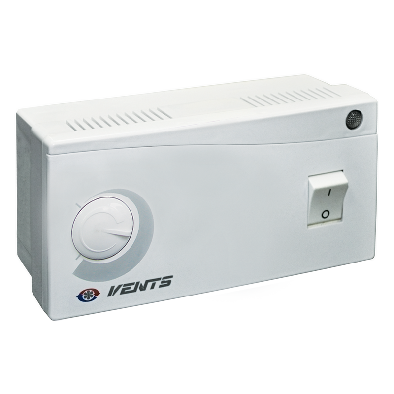
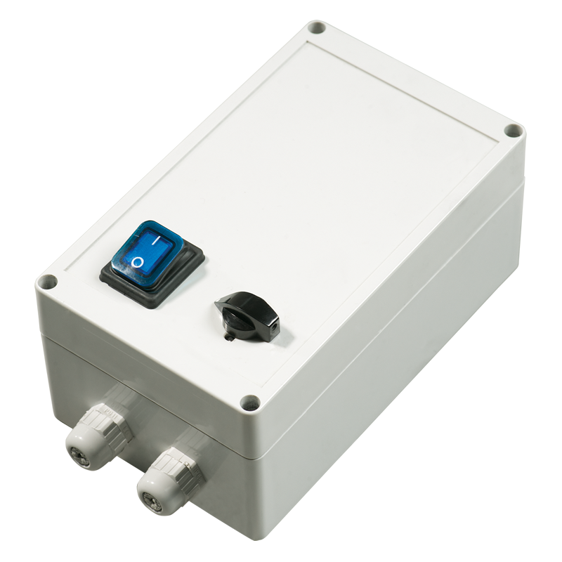
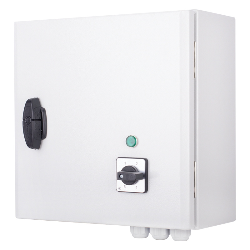
| SPEED CONTROL | |
|
|
| MOUNTING | |
|
|
|
THE FAN WITH ELECTRONIC TEMPERATURE AND CONTROL MODULE (U OPTION)
|
|
|
|
|
|
|
Control logic of the fan with the electronic temperature and speed control module
|
|
|
|
| There are three switch delay patterns for various cases: | |
|
|
 |
|
| VENTS KSA fan greenhouse ventilation example | |
| Series | Spigot diameter | Polarity | Phase | Options |
| VENTS KSA | 100; 125; 150; 160; 200 | 2, 4 | Е: single phase | U: speed controller with an electronic thermostat and a temperature sensor integrated inside an air duct. Temperature-based operation logic. Un: speed controller with an electronic thermostat and a temperature sensor fixed on a 4-meter cable. Temperature-based operation logic. U1: speed controller with an electronic thermostat and a temperature sensor integrated inside an air duct. Timer-based operation logic. U1n: speed controller with an electronic thermostat and a temperature sensor fixed on a 4-meter cable. Timer-based operation logic. U2: speed controller with an electronic thermostat and a temperature sensor integrated inside an air duct. Temperature-based switching on/off. U2n: speed controller with an electronic thermostat and a temperature sensor fixed on a 4-meter cable. Temperature-based switching on/off. R1: power cord with a mains plug. P: integrated smooth speed controller. |