| APPLICATIONS |
|
|
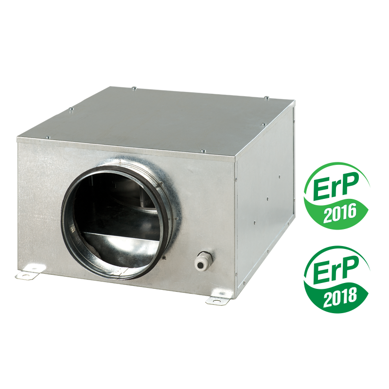
- Provision is made for installation in a premise above the suspended ceiling.
- Suitable for connection with 100, 125, 150, 160, 200, 250 and 315 mm round ducts.
|
| DESIGN |
|
|
|
| MOTOR |
-
The centrifugal impeller with back-curved blades is powered by means of 2-pole asynchronous motor with external rotor.
-
The motors are equipped with built-in thermal overheating protection with automatic restart.
-
Motor ball bearings with selective lubricating oil ensure low-noise and maintenance-free fan operation.
|
|
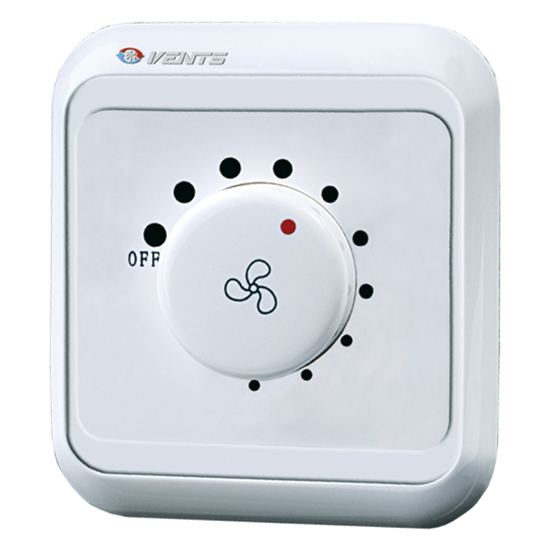
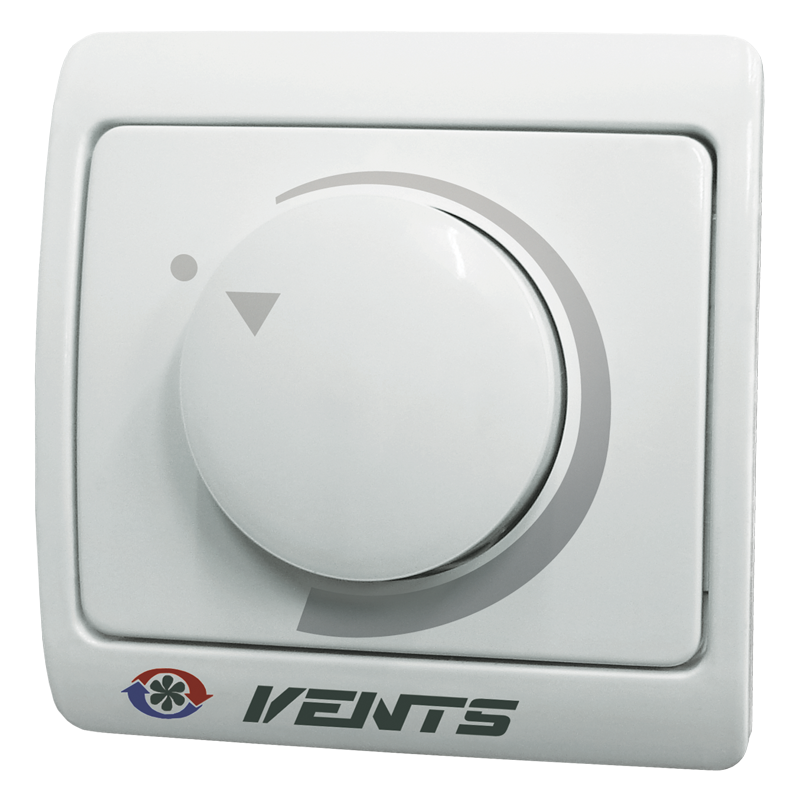
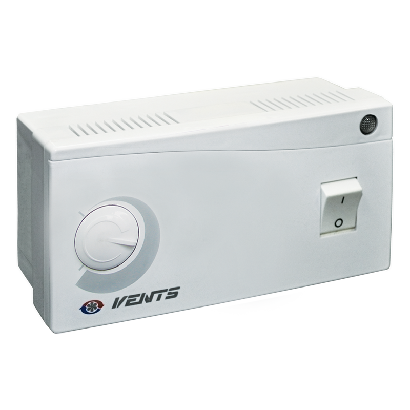
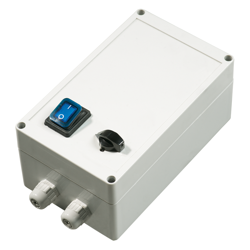
| SPEED CONTROL |
|
|
- Several fans may be connected to one speed controller provided that the total power and operating current do not exceed the rated speed controller parameters.
|
| MOUNTING |
-
The fans are designed for inline mounting inside an air duct of matching air duct diameter, in any point of the ventilation system and at any angle.
-
The fan shall be fixed to a building by means of supports, suspension brackets or fixation brackets in case of flexible connectors application.
|
|
|
The fan with electronic temperature and control module (U option)
|
|
|
- The fan with the electronic temperature and speed control module provides automatic control of the motor speed (air capacity) depending on air temperature in the air duct or in the room.
|
- The fan front panel has the following control knobs:
- speed control knob for setting the motor speed;
- thermostat control knob for setting the temperature set point;
- thermostat indicator light.
|
- The fan is available in two modifications:
- with the temperature sensor integrated inside the fan air duct (U/U1 option);
- with the external temperature sensor fixed on the cable, 4 m long (Un / U1n).
|
|
Control logic of the fan with the electronic temperature and speed control module
|
|
|
- The motor switches to the preset lower speed as the temperature drops down below the temperature set point. To avoid frequent motor speed switches when the air temperature in the duct is equal to the set temperature point, the speed switch delay is activated.
|
| There are two switch delay patterns for various cases: |
- The temperature sensor-based switch delay (U option): the motor switches to higher speed as the air temperature exceeds 2 °C above the set thermostat set point. The motor revers to the preset lower speed as the air temperature drops below the thermostat set point. This pattern is used to keep air temperature to within 2 °C. In this case the motor speed switches are rare.
|
- The timer-based switch delay (U1 option): as the air temperature exceeds the set thermostat set point, the motor switches to higher speed and the switch delay timer is activated for 5 min. The motor reverts to lower speed as the air temperature drops down below the thermostat set point and only after 5 minuts timer countdown. This pattern is used for exact air temperature control. The speed switches for the fan with U1 option are more frequent as compared to the operating logic of the fan with U option, however the minimum operating cycle at one speed is 5 minutes.
|
| Example for temperature sensor delay: |
Example for timer delay: |
- Initial conditions:
- rated speed is set as 60% of the maximum speed
- operating threshold is set as 25°С
- air temperature in the duct is 20°С
|
- Initial conditions:
- rated speed is set as 60% of the maximum speed
- operating threshold is set as 25°С
- air temperature in the duct is 20°С
|
- Fan operates with the rated speed =60%
|
- motor operates with the motor speed =60%
|
| ↓ |
↓ |
- air temperature in the duct rises
- Fan operates with the rated speed =60%
|
- The temperature in the duct rises, reaches 25°C and keeps rising
|
| ↓ |
|
- air temperature in the duct reaches 27°С
- Fan operates with the speed =100%
|
- Fan switches to the maximum speed =100% and the delay timer switches for 5 minutes on
|
| ↓ |
↓ |
- air temperature in the duct goes down
- Fan operates with the speed =100%
|
- the temperature in the duct goes down
- The fan operates with the maximum speed =100%
|
| ↓ |
↓ |
- temperature in the duct reaches 25°C again
- Fan switches to the preset rated speed =60%
|
- the temperature in the duct reaches 25°C and keeps going down
|
| |
↓ |
| |
- after the timer stops, the motor switches to the preset rated speed (=60%). After the speed switch the timer switches again for 5 minutes on
|
| |
↓ |
| |
- the temperature in the duct rises, reaches 25°C and keeps rising
|
| |
↓ |
| |
- after the timer stops, the motor switches to the maximum speed (=100%). After the speed switch the timer switches again for 5 minutes on.
|
| |
- Thus, in timer delay pattern the delay timer activates every time the fan speed changes.
|


 Domestic fans
  Industrial and commercial fans
  Single-room ventilation systems with heat recovery
  Air handling units
  Air heating systems
  Smoke extraction and ventilation
  Accessories for ventilating systems
  Electrical accessories
  Ventilation ducts and fittings
  Air distribution components
  Ventilation kits and vents